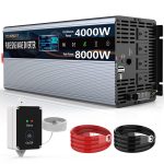

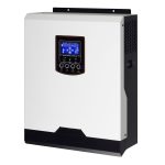


Vanonpower.com – Connecting two inverters in parallel requires using specialized parallel-capable inverters and a dedicated communication cable to synchronize their AC output phases, preventing destructive circulating currents. You cannot simply bridge the output terminals of standard, non-parallel-capable inverters, as this will lead to immediate hardware failure or fire hazards.
Understanding the Necessity of Parallel Connection
Connecting two inverters in parallel is a common strategy for homeowners and off-grid enthusiasts looking to increase their total power output. By linking two units, you effectively double the wattage capacity, allowing you to run high-load appliances like air conditioners, pumps, and power tools simultaneously. However, this configuration is technically demanding. If the two inverters are not perfectly synchronized in terms of voltage, frequency, and phase angle, they will fight each other, resulting in a massive surge of current flowing from one unit to the other.
Crucial Prerequisites Before Wiring
Before attempting any installation, you must ensure that your specific inverter models are designed for parallel operation. Most high-end off-grid inverters include a “parallel kit” or built-in parallel ports. You must verify that the firmware versions on both units are identical; running mismatched firmware can cause the internal logic to conflict, leading to system instability. Additionally, always use identical models from the same manufacturer to ensure the internal components and power ratings are perfectly matched.
Technical Requirements Comparison
| Feature | Requirement | Reasoning |
|---|---|---|
| Inverter Model | Identical (Same series) | Ensures matching impedance and logic |
| Cable Length | Identical length for AC out | Prevents voltage drop imbalances |
| Battery Bank | Common DC Bus | Maintains stable voltage for both units |
| Communication | Parallel Cable (RJ45) | Synchronizes phase and load sharing |
Step-by-Step Installation Guide
Follow these steps strictly to ensure a safe and successful parallel configuration. Always disconnect all power sources—both AC and DC—before touching any wiring terminals.
- Mount both inverters side-by-side with adequate ventilation space to prevent overheating.
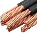
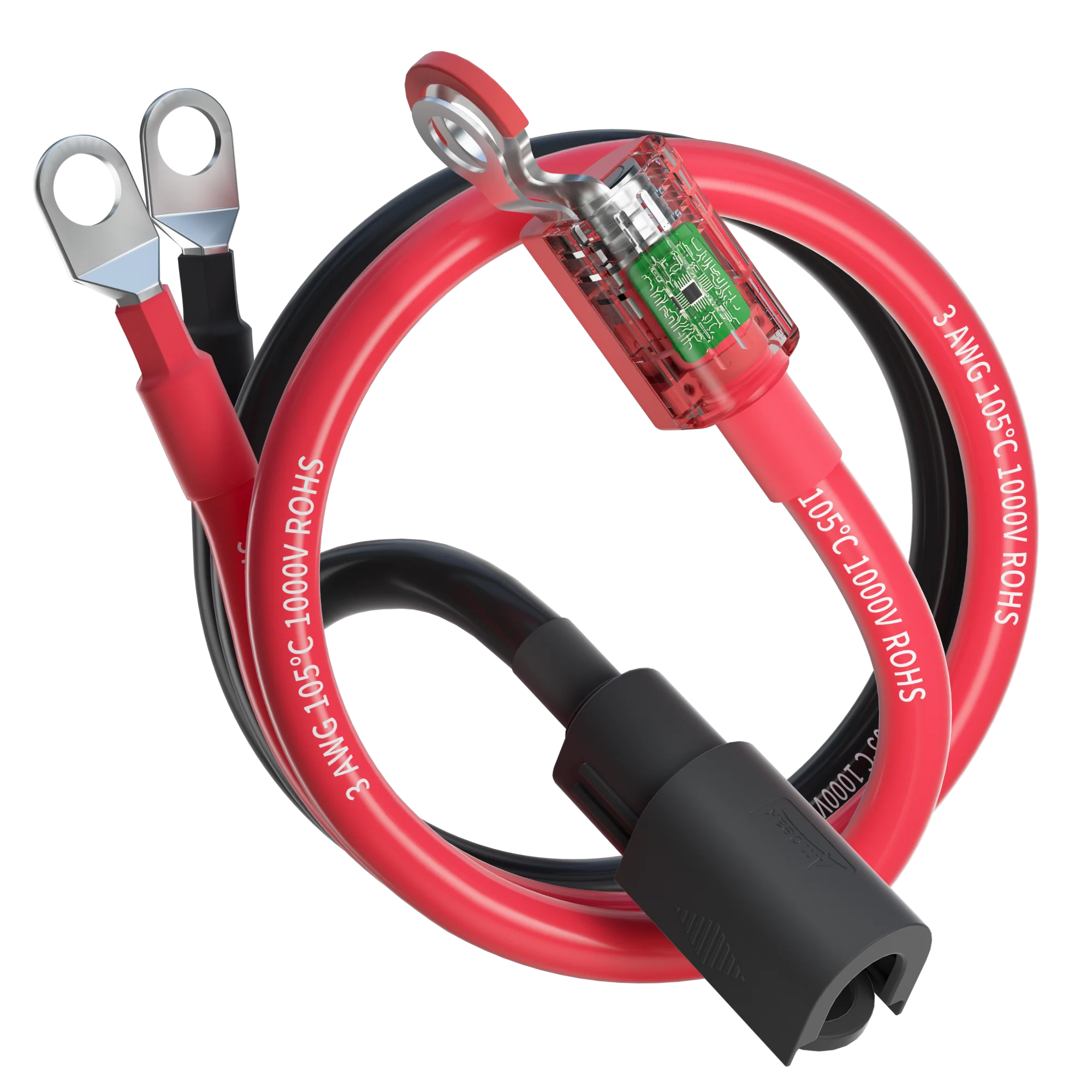
- Connect the DC input terminals of both inverters to the same battery bank using high-gauge cables of equal length to ensure balanced resistance.
- Insert the parallel communication cable between the designated RJ45 ports on both units to allow them to share data and synchronize timing.
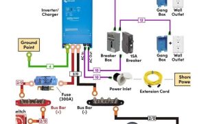
- Connect the AC output terminals (Live, Neutral, and Ground) of both inverters to a common AC distribution box or a dedicated parallel output bus bar.
- Set the configuration switches or software settings on each inverter (usually labeled “Master” and “Slave”) according to the manufacturer’s specific manual.
- Turn on the DC power to both units simultaneously, then activate the inverter switches one by one to verify that they recognize each other and display the parallel status on the screens.
Common Mistakes and Safety Risks
The most frequent error is neglecting the importance of cable sizing and length. If the AC output cable from Inverter A is three meters long and the cable from Inverter B is five meters long, the difference in resistance will cause the inverters to share the load unevenly. This leads to one inverter overloading while the other remains underutilized, eventually causing a system-wide shutdown or component burnout.
Another critical mistake is failing to use a common ground. All equipment must be bonded to the same grounding system to avoid ground loops, which can interfere with the sensitive communication signals required for synchronization. Always inspect your connections for tightness; loose connections under high current loads will generate heat, melt insulation, and create a significant fire risk.
The Role of the Communication Cable
Many users mistakenly believe that if the inverters are connected to the same battery and the same AC output line, they will automatically sync. This is false. The communication cable is the “brain” of the operation. It sends high-speed signals between the processors of both units, ensuring that the sine wave produced by Inverter A perfectly overlaps with the sine wave produced by Inverter B. Without this signal, the two units will operate out of phase, creating a short circuit condition that can destroy the output transistors instantly.
FAQ Section
Q: Can I parallel two inverters of different brands?
A: No. Different brands use proprietary communication protocols and internal architectures. Connecting them will result in synchronization failure and likely damage both units.
Q: Do I need a larger battery bank when adding a second inverter?
A: Yes. Since you are doubling your potential power output, your battery bank must be capable of handling the increased discharge current. Ensure your batteries are rated for the combined amperage of both inverters.
Q: What happens if the communication cable is disconnected during operation?
A: Most modern parallel-capable inverters are designed to shut down immediately if the communication link is lost. This is a safety feature to prevent the units from drifting out of phase while under load.
Final Considerations for System Longevity
Once your parallel system is operational, perform a load test. Start with a small load and monitor the display panels on both units to ensure they are sharing the load equally (e.g., if you have 1000W of load, each inverter should show roughly 500W). If the load sharing is significantly skewed, re-check your AC output cable lengths and the integrity of the communication cable. Maintaining a consistent temperature in your inverter room is also vital, as heat degrades the electronic components that manage the parallel synchronization, which can lead to intermittent faults over time.
📷 Photo by walmart.com