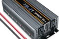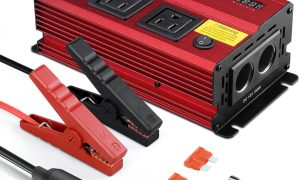





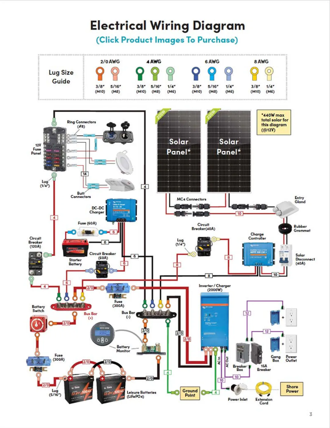
Vanonpower.com – A dedicated chassis ground for a campervan inverter is installed by connecting the inverter’s grounding lug directly to a clean, sanded metal point on the vehicle’s frame using a high-gauge copper cable and a stainless steel bolt. This connection is essential to prevent electrical shock and ensure the inverter’s safety mechanisms function correctly during a fault.
Why a Dedicated Chassis Ground is Non-Negotiable
Many DIY campervan builders assume that because the inverter is connected to the battery, it is already grounded. While the negative terminal of the battery eventually connects to the chassis, a dedicated ground for the inverter provides a secondary, low-resistance path for fault currents. If an internal insulation failure occurs within the inverter, the chassis ground directs the current safely to the frame, preventing the metal casing of your inverter from becoming energized and dangerous to touch.
Neglecting this step creates a significant safety risk. In the event of a short circuit, an ungrounded inverter case could hold a high voltage, turning your appliances and the inverter housing itself into a shock hazard. Furthermore, many modern inverter-chargers require a proper earth connection to synchronize their internal GFCI (Ground Fault Circuit Interrupter) protection systems with your AC outlet circuit.
Essential Tools and Materials
Before beginning the installation, ensure you have the correct materials. Using automotive-grade components is vital, as campervans are subject to constant vibration and temperature fluctuations.
| Component | Specification Requirement |
|---|---|
| Grounding Cable | Same gauge as the DC input cables (typically 2 AWG or 4 AWG) |
| Ring Terminals | Tinned copper for corrosion resistance |
| Attachment Hardware | Stainless steel bolt, nut, and star-tooth washers |
| Surface Prep | Fine-grit sandpaper or a wire wheel attachment |
Step-by-Step Installation Guide
Follow these steps to ensure a secure, low-resistance connection that meets electrical safety standards for mobile installations.
- Locate a sturdy, non-structural part of the vehicle’s metal chassis as close to the inverter as possible. Ensure this location is not near fuel lines, brake lines, or electrical wiring.
- Use a wire wheel or sandpaper to strip away all paint, rust, and primer from the metal surface until you reach bare, shiny steel. A poor connection here will render the ground ineffective.
- Measure and cut your grounding cable to length, crimping high-quality tinned copper ring terminals onto both ends. Use a professional-grade hydraulic crimper rather than a hammer-style tool to ensure a gas-tight connection.
- Apply a thin layer of dielectric grease or conductive anti-corrosion paste to the bare metal surface to prevent future oxidation.
- Bolt the cable to the chassis using a stainless steel bolt and a star-tooth washer; the washer is critical because its teeth bite into the metal to create a mechanical, vibration-proof electrical bond.
- Connect the opposite end of the cable to the grounding lug on the inverter chassis, ensuring all connections are tightened to the manufacturer’s specified torque settings.
Common Mistakes to Avoid
One of the most frequent errors is relying on a pre-existing screw that holds a plastic panel in place. These screws rarely provide a true path to the vehicle’s metal frame. You must ensure your ground point is physically part of the structural chassis. Another common mistake is failing to account for corrosion. Over time, moisture beneath the vehicle can cause rust to form between the cable lug and the metal, effectively disconnecting your ground. Always seal the connection with a protective spray or heavy-duty heat shrink.
Additionally, do not daisy-chain ground wires. Each high-power device should ideally have its own dedicated path to the chassis. Running multiple devices through a single, thin ground wire can cause voltage drops and potential heating issues under heavy electrical loads.
Signs of an Improper Ground
If you notice a slight tingling sensation when touching the metal housing of your inverter, or if your GFCI outlets are tripping randomly without an obvious load, your ground connection is likely compromised. These are warning signs that the inverter is not successfully shunting stray voltage. A multimeter can be used to check for continuity between the inverter chassis and the vehicle frame; a resistance reading of near zero ohms is the gold standard.
Frequently Asked Questions
Q: Can I use the negative battery terminal instead of the chassis?
A: While the negative battery cable is grounded, a dedicated chassis ground provides a localized safety path. It is standard practice to maintain both connections to ensure the inverter case is always referenced to the vehicle’s earth potential.
Q: Do I need to use a specific cable color for the ground?
A: Yes, standard practice dictates using green or green/yellow striped insulation for grounding wires. If those are unavailable, use black cable and wrap both ends with green electrical tape to clearly identify the cable’s purpose for future maintenance.
Q: How often should I check the ground connection?
A: You should inspect the connection at least once a year. Check for signs of rust, loose bolts, or frayed insulation. Since campervans experience constant road vibration, ensuring the bolt remains tight is a critical part of routine electrical maintenance.
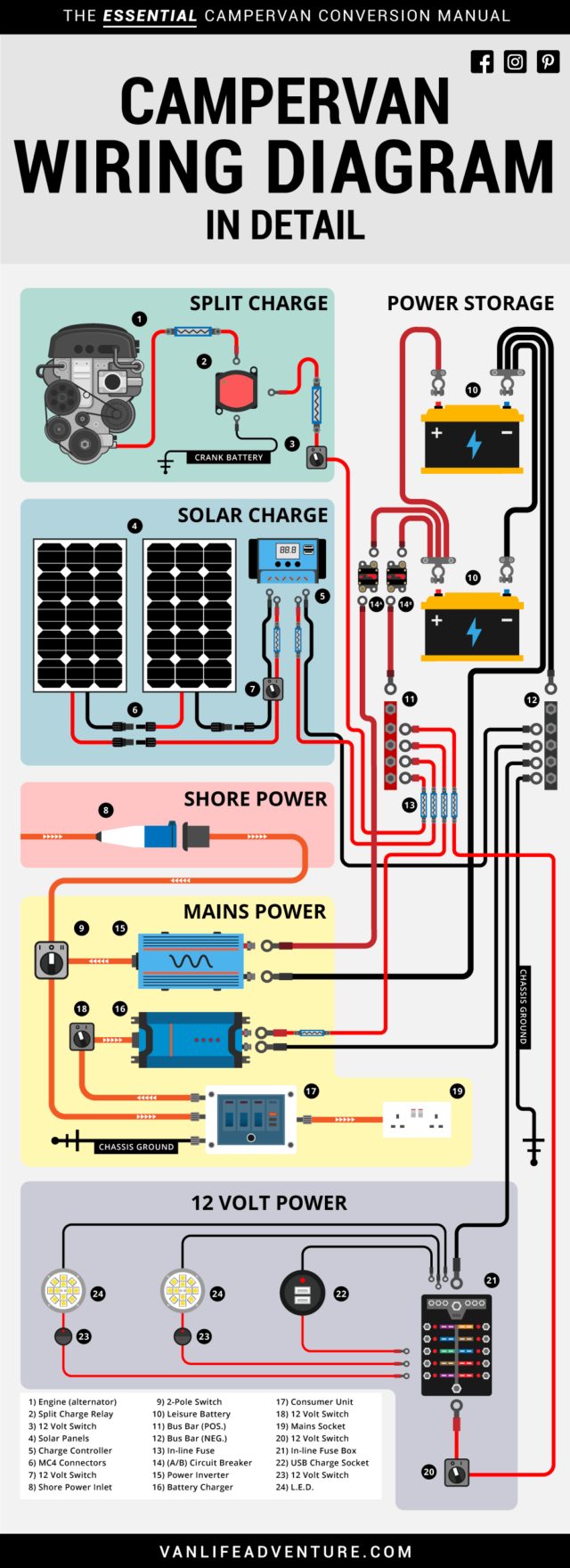
📷 Photo by moowiring.com
Final Considerations for Safety
Always disconnect your battery bank before performing any work on the inverter’s grounding system. Even when the inverter is turned off, the DC input terminals remain live and capable of delivering significant current. By following these professional installation practices, you create a robust electrical system that protects both your expensive equipment and your personal safety while on the road.
Read also: Can You Connect Solar Panels Directly to an Inverter?
📷 Photo by etsy.com