


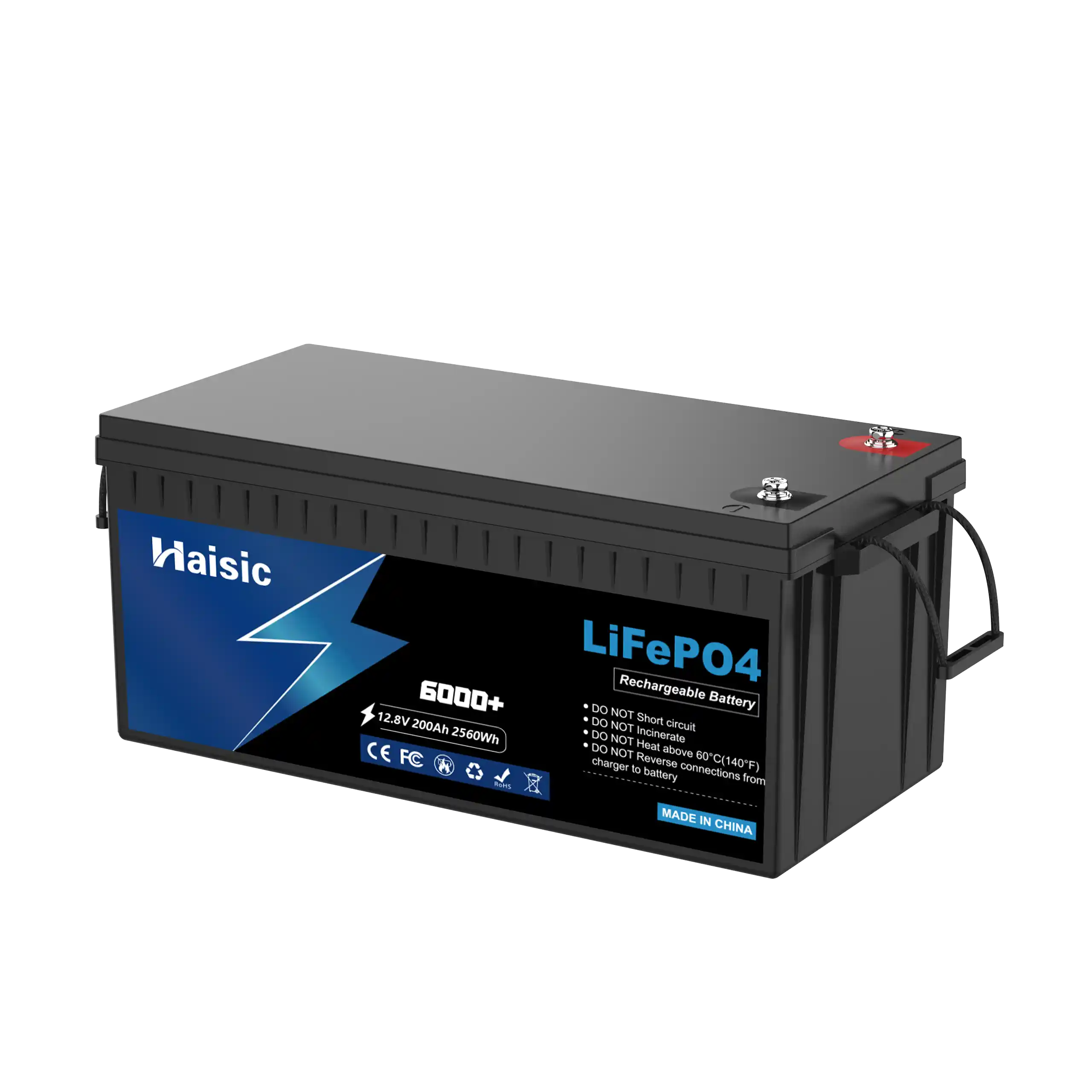
Vanonpower.com – The maximum discharge current of a LiFePO4 battery is determined by multiplying its capacity (Ah) by its specific C-rating, which dictates the safe threshold for power delivery without risking thermal runaway or permanent cell degradation.
Understanding C-ratings is the most critical aspect of battery management for anyone deploying lithium iron phosphate systems. Whether you are building an off-grid solar array, powering an electric vehicle, or designing a high-draw industrial tool, miscalculating discharge limits is the primary cause of premature battery failure and safety hazards.
What Exactly is a C-Rating?
A C-rating represents the rate at which a battery is discharged relative to its maximum capacity. The “C” stands for “capacity.” If a battery has a capacity of 100Ah, a 1C discharge rate means the battery can deliver 100 Amps for one hour. A 0.5C rate would mean 50 Amps for two hours, while a 2C rate would mean 200 Amps for 30 minutes.
It is vital to distinguish between continuous discharge and peak (or pulse) discharge ratings. Continuous discharge refers to the current a battery can supply indefinitely without exceeding its thermal limits. Peak discharge, often lasting only a few seconds, allows for high-current surges required by motors or compressors during startup.
Why LiFePO4 Differs from Other Chemistries
LiFePO4 is favored for its chemical stability, but it is not immune to the laws of physics. Unlike lead-acid batteries, which suffer from the Peukert effect—where capacity drops drastically at high discharge rates—LiFePO4 batteries maintain a very flat voltage discharge curve. This makes them highly efficient, but it also hides the signs of stress until the cell approaches a critical state.
If you push a LiFePO4 battery beyond its rated maximum discharge current, the internal resistance causes rapid heat generation. Because the electrolyte is organic, excessive heat can lead to the breakdown of the internal separator, potentially causing a short circuit. Always consult the manufacturer’s datasheet, as chemistry formulations can vary between manufacturers.
📷 Photo by ayaatech.com
Quick Reference: Discharge Rate Impact
| Discharge Rate (C) | Current (100Ah Battery) | Runtime (Theoretical) | Typical Application |
|---|---|---|---|
| 0.5C | 50 Amps | 120 Minutes | Solar storage, LED lighting |
| 1.0C | 100 Amps | 60 Minutes | Inverters, small motors |
| 2.0C | 200 Amps | 30 Minutes | High-draw power tools |
| 3.0C (Peak) | 300 Amps | 10 Seconds | Motor starting surges |
Calculating Your System Requirements
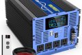
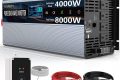
To avoid damaging your battery bank, you must calculate the maximum load of your appliances. If you have an inverter rated for 3000W, you must calculate the current draw at the battery level. For a 12V system, 3000W divided by 12V equals 250 Amps. If your battery is rated at 100Ah with a 1C rating (100A), you cannot run that inverter at full power without damaging the battery. You would need at least three 100Ah batteries in parallel to safely handle that load.
Steps to Safely Configure Your Discharge Setup
- Identify the maximum continuous wattage of all connected devices (inverters, chargers, motors).
- Calculate the total amperage by dividing the total wattage by the nominal voltage of your battery bank.
- Check the manufacturer’s datasheet for the “Maximum Continuous Discharge Current” rating.
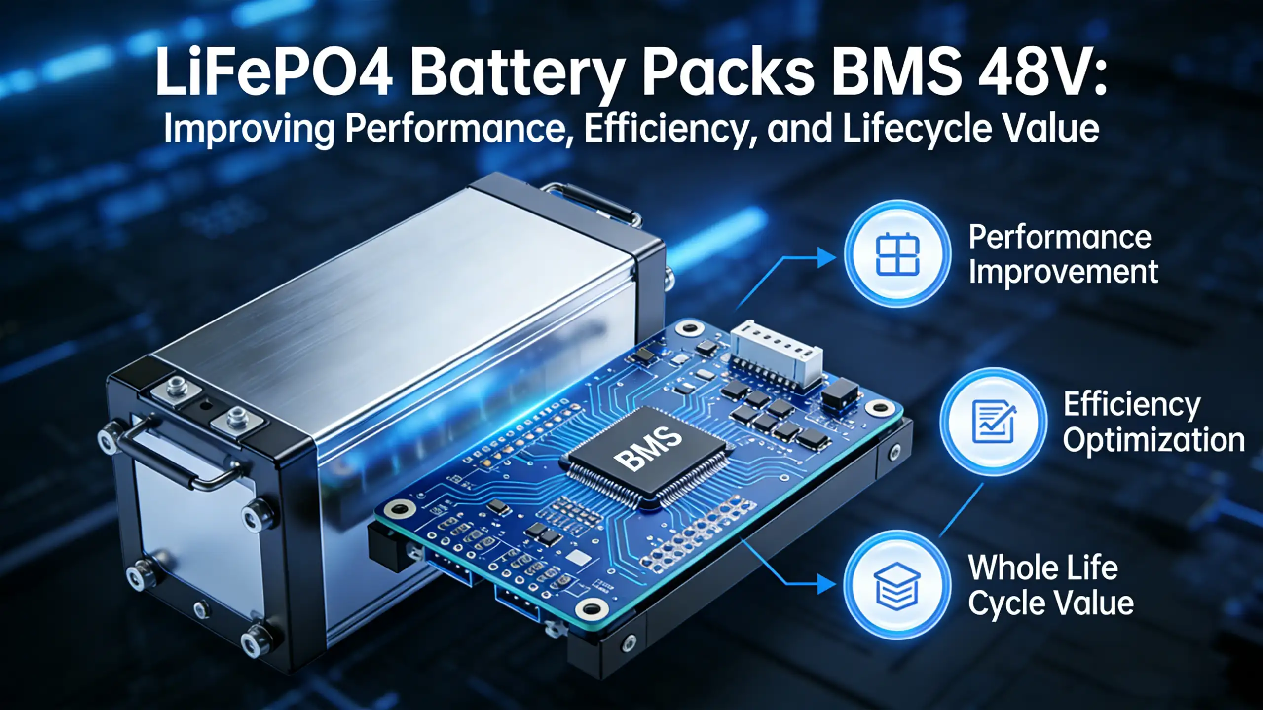
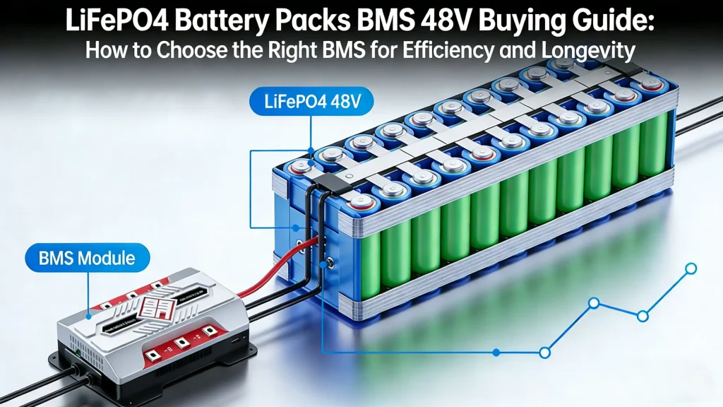
- Select a Battery Management System (BMS) that matches or is slightly lower than the battery’s maximum discharge rating to act as a safety cutoff.
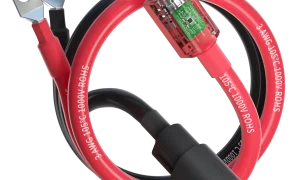
- Ensure your cabling gauge is sufficient to handle the calculated amperage to prevent voltage drop and overheating at the terminals.
- Monitor the battery temperature during the first few high-load cycles to ensure it stays within the recommended operating range.
Common Mistakes and Risks
The most common error is neglecting the “Pulse” duration. Many spec sheets claim a high discharge rate, but only for a duration of 3–5 seconds. If you attempt to sustain a pulse-level current, the BMS will likely trip to protect the cells, causing your system to shut down unexpectedly. This is particularly problematic in critical infrastructure or life-support applications.
Another risk is the “Voltage Sag.” While LiFePO4 has a flat curve, drawing current near the maximum limit will cause the voltage to sag significantly under load. This can trigger low-voltage alarms on inverters even if the battery is technically “charged.” Keep your load well within 70% of the maximum continuous rating to maximize the lifespan of your cells.
Thermal Management
Heat is the enemy of longevity. Even if the BMS allows a 1C discharge, doing so in a confined, unventilated space will accelerate the aging of the electrolyte. Ensure that your battery installation allows for passive airflow or active cooling if the discharge current consistently exceeds 0.5C. Proper spacing between cells or battery modules is essential to prevent thermal runaway in the event of a cell fault.
Read also: How to Charge LiFePO4 Batteries with an Alternator
Q: Can I connect batteries in parallel to increase the discharge current?
A: Yes. When you connect batteries in parallel, you add their capacities together, which effectively increases the total maximum discharge current available to your system. For example, two 100Ah 1C batteries in parallel provide 200Ah of capacity and a 200A maximum discharge limit.
📷 Photo by ayaatech.com
Q: What happens if my BMS trips during a high-discharge event?
A: The BMS is programmed to disconnect the battery to prevent permanent damage. If this happens, you must reduce the load on the system before the BMS will reset or allow power flow again. Frequently tripping the BMS indicates that your battery bank is undersized for your power requirements.
Q: Does temperature affect the maximum discharge current?
A: Absolutely. At very low temperatures (near freezing), the internal resistance of LiFePO4 cells increases significantly. You should derate your maximum discharge current by 50% or more in freezing conditions to prevent excessive voltage sag and internal cell stress.
By respecting the C-rating and planning your system based on continuous rather than peak loads, you ensure that your LiFePO4 investment provides years of reliable service. Always prioritize a robust BMS and high-quality cabling to bridge the gap between your energy storage and your power needs.
📷 Photo by haisicstorage.com