


Vanonpower.com – Wiring solar panels in series increases the total voltage while keeping amperage constant, whereas parallel wiring increases the total amperage while maintaining the same voltage as a single panel.
Understanding the fundamental difference between series and parallel configurations is essential for designing an efficient solar power system. The choice between these two methods dictates how your charge controller functions, the thickness of the wiring required, and how the system performs under partial shading conditions.
The Mechanics of Series Wiring
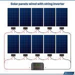
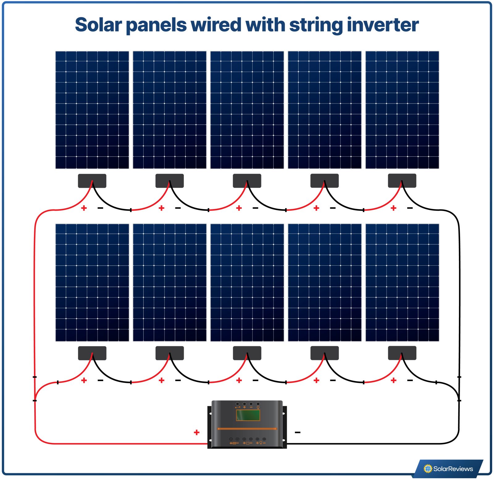
When you connect solar panels in series, you connect the positive terminal of one panel to the negative terminal of the next. This creates a single path for the electrical current to flow through all panels. In this configuration, the voltages of the panels add up, but the current (amperage) remains the same as a single panel.
For example, if you have three 12-volt panels that each produce 5 amps, a series connection results in a 36-volt system that still produces 5 amps. This is highly beneficial when you need to transmit power over longer distances, as higher voltage reduces energy loss through heat in the cables. However, the downside is that if one panel is shaded, the entire string’s performance can drop to the level of the shaded panel.
The Mechanics of Parallel Wiring
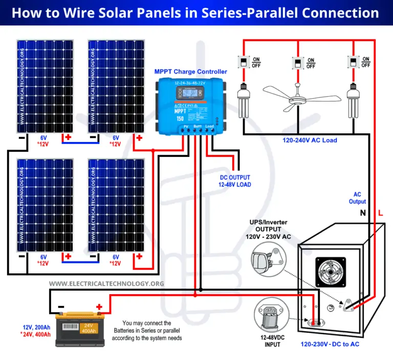
Parallel wiring involves connecting all positive terminals together and all negative terminals together. In this setup, the amperage of the panels adds up, while the voltage remains consistent with that of a single panel. Using the same example of three 12-volt, 5-amp panels, a parallel connection results in a 12-volt system with 15 amps of total current.
This configuration is superior for systems prone to partial shading. If one panel is covered by a tree branch or debris, the other panels continue to operate at full capacity. The primary drawback is that higher amperage requires significantly thicker, more expensive copper wiring to prevent overheating and voltage drop.
Comparison Table: Series vs. Parallel
| Feature | Series Connection | Parallel Connection |
|---|---|---|
| Voltage | Additive (Sum of all panels) | Constant (Same as one panel) |
| Amperage | Constant (Same as one panel) | |
| Shading Impact | High (System performance drops) | Low (Unaffected panels continue) |
| Wire Gauge | Thinner (Lower current) | Thicker (Higher current) |
| Best Use Case | Long cable runs, MPPT controllers | Partial shade, PWM controllers |
How to Properly Wire Your Solar Array
Before beginning any electrical work, ensure your solar panels are covered or disconnected from the charge controller to prevent electrical shock. Follow these steps to determine your configuration:
- Check your charge controller specifications to see the maximum input voltage and amperage it can handle.
- If using an MPPT controller, series wiring is often preferred because these controllers can convert excess voltage into usable charging current.
- If you are using a PWM controller, ensure your panel voltage matches the battery bank voltage, which usually necessitates parallel wiring.
- Connect the panels using MC4 connectors, ensuring you click them firmly into place to maintain a weather-tight seal.
- Use a multimeter to measure the output at the end of the main cables before connecting to your solar charge controller to verify the expected voltage or amperage.
Common Mistakes and Practical Risks
One of the most frequent errors installers make is mixing panels of different wattages or brands in the same string. In a series connection, the entire string is throttled by the weakest panel. If you must use different panels, it is often safer to wire them in parallel, provided you use blocking diodes to prevent back-feeding, which can damage the panels.
📷 Photo by moowiring.com
Another risk involves wire gauge sizing. As you increase the amperage in a parallel system, you must ensure your cables are rated to handle the load. Using wire that is too thin will lead to high resistance, which causes the cables to heat up, potentially melting insulation and creating a fire hazard.
The Role of Charge Controllers
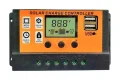
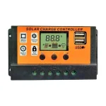
The type of charge controller you own is a deciding factor in how you should wire your panels. MPPT (Maximum Power Point Tracking) controllers are designed to handle high voltage inputs. They efficiently down-convert high voltage from a series array into the lower voltage required by your battery bank. Conversely, if you have a budget-friendly PWM (Pulse Width Modulation) controller, you are restricted to a voltage range very close to the battery voltage, making parallel wiring the standard choice.
Always inspect your connections annually. Corrosion at the contact points can lead to increased resistance, which is exacerbated in high-amperage parallel systems. Keeping your connections clean and tight ensures the longevity of your solar investment.
FAQ
Q: Can I mix series and parallel wiring in one system?
A: Yes, this is called a series-parallel or “grid” configuration. It is used to balance the benefits of higher voltage with the shading tolerance of parallel connections, often used in large residential arrays.
Q: Will higher voltage from series wiring damage my battery?
A: Not directly. The solar charge controller acts as a buffer between the panels and the battery, stepping down the voltage to a safe level for charging.
Q: What happens if I exceed the voltage limit of my controller?
A: Exceeding the maximum input voltage of a charge controller will likely cause internal damage or total failure of the device. Always check the controller’s data sheet before finalizing your wiring.
📷 Photo by wiringtoday.com