

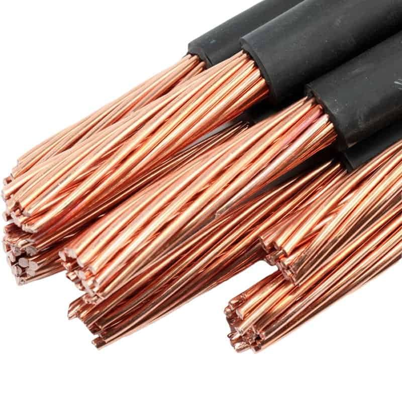
Vanonpower.com – Inverter cables become hot primarily due to excessive electrical resistance caused by undersized wire gauges, loose terminal connections, or high current draw exceeding the cable’s thermal capacity, leading to significant voltage drop and potential fire hazards.
When an inverter pulls power from a battery bank, it draws high amperage to convert DC to AC. If the cables are not sized correctly for the distance and the load, the resistance within the wire turns electrical energy into heat. This phenomenon, known as Joule heating, is not just a sign of inefficiency; it is a critical warning that your electrical system is under stress.
The Physics Behind Overheating
Every electrical conductor has a degree of resistance. As current flows through a wire, some energy is lost as heat. The heat generated is proportional to the square of the current multiplied by the resistance. When you use cables that are too thin, you increase the resistance. The result is a dual problem: you lose usable power (voltage drop) and the excess energy manifests as heat, which can melt insulation and damage your inverter terminals.
Voltage drop is the silent killer of battery systems. If your inverter requires 12V but the cable resistance causes a 1.5V drop, the inverter may shut down prematurely, falsely signaling a “low battery” state even when the battery has plenty of capacity left. This inefficiency forces the system to work harder, generating even more heat in a feedback loop that leads to equipment failure.
Common Causes of Excessive Heat
The most common culprit is simply using a wire gauge that is too small for the amperage requirement. Many beginners look at the inverter’s peak power rating rather than its continuous current draw. You must calculate the current based on the maximum continuous load and the total round-trip distance of the wire from the battery to the inverter and back.
Another major factor is poor contact surfaces. If the cable lug is not bolted tightly to the terminal, the small air gap creates high resistance at the connection point. This is often why the heat feels most intense right at the terminal lug rather than along the length of the wire. Corrosion on terminals also acts as an insulator, forcing the current to struggle to pass through, which generates significant heat.
Comparison of Cable Gauges and Capacity
| AWG Size | Max Amperage (Recommended) | Typical Application |
|---|---|---|
| 4 AWG | 85 Amps | Small inverters up to 1000W |
| 2 AWG | 115 Amps | 1500W to 2000W Inverters |
| 1/0 AWG | 150 Amps | 2500W to 3000W Inverters |
| 4/0 AWG | 230 Amps | High-capacity 4000W+ Systems |
Steps to Diagnose and Fix Overheating Cables
If you notice your cables are hot to the touch, you must address the issue immediately to prevent a fire. Follow these steps to rectify the problem:
- Turn off the inverter and disconnect the cables from the power source to ensure safety.
- Inspect the physical condition of the wires; look for melted insulation, brittle casing, or discoloration, which indicate the cable has already suffered heat damage and must be replaced.
- Check the terminal connections for tightness; use a wrench to ensure they are torqued according to the manufacturer’s specifications.
- Clean the battery terminals and cable lugs with a wire brush to remove any oxidation or corrosion that increases electrical resistance.
- Calculate your actual load and distance; if the cable gauge is below the recommended size for your inverter’s continuous wattage, replace the entire cable run with a thicker, properly rated gauge.
- Re-test the system under a moderate load for 30 minutes and monitor the temperature of the cables using an infrared thermometer.
Risks of Ignoring Cable Heat
Ignoring hot cables is a recipe for disaster. Beyond the obvious risk of melting the wire insulation and causing a short circuit, the heat can travel into the inverter itself. This can damage the internal capacitors and sensitive electronic components, effectively destroying the inverter. Furthermore, the heat represents a “voltage drop” that prevents your appliances from receiving the stable power they need to operate efficiently.
In many cases, the heat is a symptom of a system that is being pushed beyond its design limits. If you find your cables getting hot during normal operation, your entire electrical system is likely undersized. This includes the battery bank’s ability to discharge at that rate and the inverter’s capacity to handle the load.
Best Practices for Installation
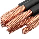
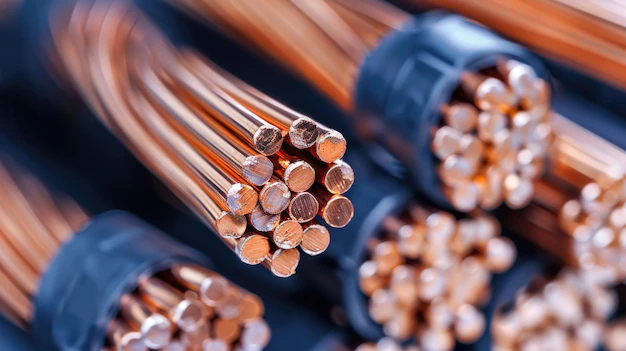
Always use high-quality, fine-stranded copper welding cable rather than stiff, solid-core wire. Welding cable is designed for flexibility and high current-carrying capacity, making it ideal for mobile or vibrating environments like RVs and boats. Ensure that the length of the cable is kept as short as possible; the longer the wire, the higher the voltage drop.
If you must run long distances, you must increase the gauge size to compensate for the added resistance. Never use household Romex wiring for DC inverter connections, as it is not rated for the high amperage and vibration conditions found in mobile power systems.
📷 Photo by freepik.com
Frequently Asked Questions
Q: Is it normal for cables to be slightly warm during operation?
A: A very slight, barely perceptible warmth is common when running high loads, but if the cable is hot enough to be uncomfortable to hold, it is a sign of an undersized wire or a poor connection that requires immediate attention.
Q: Does the material of the cable matter?
A: Yes, always use pure copper cables. Copper-clad aluminum (CCA) is cheaper but has higher resistance, which means it will get hotter and cause a greater voltage drop than pure copper for the same gauge size.
Q: How do I calculate the correct gauge if I am unsure?
📷 Photo by chunbincable.en.made-in-china.com
A: Use an online voltage drop calculator. You will need to input the total wattage of your inverter, the system voltage (12V, 24V, or 48V), and the total length of the positive and negative cables added together.
📷 Photo by storage.googleapis.com